Page 16 - Mirjam-Theelen-Degradation-of-CIGS-solar-cells
P. 16
Chapter 1
bandgap of 1.67 eV. It has been empirically shown that a Ga/(In+Ga) ratio of 20–
35%, resulting in a bandgap of approximately 1.15–1.25 eV gives the best solar
cell efficiencies. Higher gallium contents will lead to a higher bandgap, but do
generally not lead to large increases in Voc [10]. Cu(In,Ga)Se2 absorbers have the
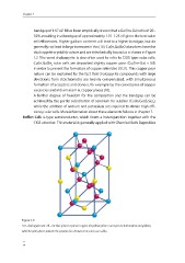
chalcopyrite crystal structure and are tetrahedrally bound as is shown in Figure
1.7. The word chalcopyrite is also often used to refer to CIGS type solar cells.
Cu(In,Ga)Se solar cells are deposited slightly copper poor (Cu/(In+Ga) ≈ 0.9)
2
in order to prevent the formation of copper selenides [10,11]. This copper poor
nature can be explained by the fact that chalcopyrite compounds with large
deviations from stoichiometry are heavily compensated, with simultaneous
formation of acceptors and donors, for example by the coexistence of copper
vacancies and indium atom at copper places [10].
A further degree of freedom for the composition and the bandgap can be
achieved by the partial substitution of selenium for sulphur (Cu(In,Ga)(S,Se)),
2
while the addition of sodium and potassium are required to obtain high effi-
ciency solar cells. More information about these elements follows in chapter 7.
Buffer: CdS: n-type semiconductor, which forms a heterojunction together with the
CIGS absorber. This material is generally applied with Chemical Bath Deposition
Figure 1.7:
CIGS chalcopyrite unit cell – the blue spheres represent copper, the yellow spheres can represent both indium and gallium,
while the pink spheres indicate the positions for selenium or in some cases sulfur.
14
bandgap of 1.67 eV. It has been empirically shown that a Ga/(In+Ga) ratio of 20–
35%, resulting in a bandgap of approximately 1.15–1.25 eV gives the best solar
cell efficiencies. Higher gallium contents will lead to a higher bandgap, but do
generally not lead to large increases in Voc [10]. Cu(In,Ga)Se2 absorbers have the
chalcopyrite crystal structure and are tetrahedrally bound as is shown in Figure
1.7. The word chalcopyrite is also often used to refer to CIGS type solar cells.
Cu(In,Ga)Se solar cells are deposited slightly copper poor (Cu/(In+Ga) ≈ 0.9)
2
in order to prevent the formation of copper selenides [10,11]. This copper poor
nature can be explained by the fact that chalcopyrite compounds with large
deviations from stoichiometry are heavily compensated, with simultaneous
formation of acceptors and donors, for example by the coexistence of copper
vacancies and indium atom at copper places [10].
A further degree of freedom for the composition and the bandgap can be
achieved by the partial substitution of selenium for sulphur (Cu(In,Ga)(S,Se)),
2
while the addition of sodium and potassium are required to obtain high effi-
ciency solar cells. More information about these elements follows in chapter 7.
Buffer: CdS: n-type semiconductor, which forms a heterojunction together with the
CIGS absorber. This material is generally applied with Chemical Bath Deposition
Figure 1.7:
CIGS chalcopyrite unit cell – the blue spheres represent copper, the yellow spheres can represent both indium and gallium,
while the pink spheres indicate the positions for selenium or in some cases sulfur.
14