Page 102 - Mirjam-Theelen-Degradation-of-CIGS-solar-cells
P. 102
Chapter 3
J
+
J ph J d V
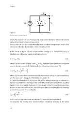
Figure 3.7 -
Electrical circuit of an ideal solar cell.
where A is the solar cell area. Analogously, other current densities (below) can also be
derived from their corresponding current.
Since a solar cell can also be considered a diode, an electrical equivalent circuit of an
ideal solar cell under illumination is depicted in Figure 3.7.
In the circuit in Figure 3.7, the current density–voltage (J-V) characteristics of p–n
junction solar cells under steady state illumination is:
=− ph + (3.2)
JJJ d
where J is the current density, while J and J represent photogenerated and diode
ph
d
current density respectively. Additionally, the following relation exists [4]:
qV
1
JJJe=− +− (3.3)
kT
o
ph
where J is the saturation current density, V is the terminal voltage T is the temperature,
o
q is the elementary charge, k is the Boltzmann constant.
This ideal diode equation (3.3) assumes that all the recombination occur via band-to-
band or recombination via traps in the bulk of the device. In reality, there are other
modes mode of recombination so solar cells do not follow the ideal diode equation.
In order to take this drift from the ideal behaviour into account, the ideality factor (n)
is added to equation (3.3), leading to:
qV
JJe=−1 (3.4)
nkT
d
0
In the case of a non-ideal solar cell, the ideality factor will be larger than 1.
R
To complete the model, some resistive effects should be included: the series
s
100
J
+
J ph J d V
Figure 3.7 -
Electrical circuit of an ideal solar cell.
where A is the solar cell area. Analogously, other current densities (below) can also be
derived from their corresponding current.
Since a solar cell can also be considered a diode, an electrical equivalent circuit of an
ideal solar cell under illumination is depicted in Figure 3.7.
In the circuit in Figure 3.7, the current density–voltage (J-V) characteristics of p–n
junction solar cells under steady state illumination is:
=− ph + (3.2)
JJJ d
where J is the current density, while J and J represent photogenerated and diode
ph
d
current density respectively. Additionally, the following relation exists [4]:
qV
1
JJJe=− +− (3.3)
kT
o
ph
where J is the saturation current density, V is the terminal voltage T is the temperature,
o
q is the elementary charge, k is the Boltzmann constant.
This ideal diode equation (3.3) assumes that all the recombination occur via band-to-
band or recombination via traps in the bulk of the device. In reality, there are other
modes mode of recombination so solar cells do not follow the ideal diode equation.
In order to take this drift from the ideal behaviour into account, the ideality factor (n)
is added to equation (3.3), leading to:
qV
JJe=−1 (3.4)
nkT
d
0
In the case of a non-ideal solar cell, the ideality factor will be larger than 1.
R
To complete the model, some resistive effects should be included: the series
s
100