Page 111 - Mirjam-Theelen-Degradation-of-CIGS-solar-cells
P. 111
Temperature dependency of the electrical parameters of CIGS solar cells
metallic grid for a better collection of the current, which is also used for cells in
full scale modules. Sodium was added via co-evapouration in a late stage of the
CIGS deposition process. The amount of sodium was controlled by tuning the NaF
crucible temperature.
In the rest of the chapter, the samples are divided into three global categories, based on
substrate and interconnection technology, as is shown in Table 4.1.
(a) (d) μm
μm
μm
μm
μm
μm
(b) (c)
(g) (e)
(f)
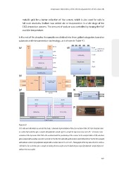
Figure 4.1
CIGS cells and cell holders as used in this study: schematic representation of the cross-section of the CIGS test structures (not
to scale) of (a) soda lime glass samples (d) polyimide samples (g) SLG sample for two interconnected cells -Schematic repre-
sentation of the top view of the CIGS cells combined with the positioning of the contact to the sample holder of: (b) soda lime
glass sample with a surface area of 0.32±0.02 cm for the SLG cells with gold contacts and 0.48±0.04 cm for the SLG samples
2
2
with indium contacts (e) polyimide sample with a surface area of 5.1±0.1 cm - Photograph of the top view of a CIGS cell in a
2
cell holder of (c) soda lime glass sample, including thermocouple attached with kapton tape (f) polyimide sample (depicted
without thermocouple).
109
metallic grid for a better collection of the current, which is also used for cells in
full scale modules. Sodium was added via co-evapouration in a late stage of the
CIGS deposition process. The amount of sodium was controlled by tuning the NaF
crucible temperature.
In the rest of the chapter, the samples are divided into three global categories, based on
substrate and interconnection technology, as is shown in Table 4.1.
(a) (d) μm
μm
μm
μm
μm
μm
(b) (c)
(g) (e)
(f)
Figure 4.1
CIGS cells and cell holders as used in this study: schematic representation of the cross-section of the CIGS test structures (not
to scale) of (a) soda lime glass samples (d) polyimide samples (g) SLG sample for two interconnected cells -Schematic repre-
sentation of the top view of the CIGS cells combined with the positioning of the contact to the sample holder of: (b) soda lime
glass sample with a surface area of 0.32±0.02 cm for the SLG cells with gold contacts and 0.48±0.04 cm for the SLG samples
2
2
with indium contacts (e) polyimide sample with a surface area of 5.1±0.1 cm - Photograph of the top view of a CIGS cell in a
2
cell holder of (c) soda lime glass sample, including thermocouple attached with kapton tape (f) polyimide sample (depicted
without thermocouple).
109