Page 135 - Mirjam-Theelen-Degradation-of-CIGS-solar-cells
P. 135
Degradation mechanisms of the molybdenum back contact
On the other hand, at high pressures, the number of collisions of sputtered atoms with
argon atoms increase, hereby decreasing the energy of the sputtered atoms when they
reach the substrate. Molybdenum films then get a more porous columnar molybdenum
grain growth with larger intergranular areas [3], probably containing a mixture of
MoO and Na MoO •2H O as reported in reference [15] and shown in Figure 5.2a. This
2
4
3
2
intergranular material causes a higher resistivity. However, since the arriving atoms do
not reorganise during the sputtering process, the adhesion is good.
When film porosity does not increase with sputter power, this can be attributed to
compressive forces which might be associated with absorption of impurities like O, H
and OH on the increased grain surface, but this was not observed in this study.
Since both good adhesion and low resistivity are required, often a molybdenum
bilayer or multilayer is used. The first layer is sputtered at high pressure for good
adhesion, while the second layer is sputtered at low pressure in order to obtain a low
resistivity.
For the ‘selenisation and pressure’ study, three sputtering pressures were chosen:
low (2 mTorr), medium (10 mTorr) and high (15 mTorr). For the ‘lift-off’ experiment, the
first layer of the bilayer was deposited at very high pressure (25 mTorr), while the top
stacks were deposited at either low pressure (2 mTorr) or high pressure (15 mTorr)
Presence of selenium
Molybdenum dichalcogenides, like MoSe [1] are often observed in CIGS type solar
2
cells, since the molybdenum reacts with selenium during the deposition process. This
material functions as an interlayer and influences the adhesion of the absorber to the
molybdenum. It is a layer compound consisting of a molybdenum layer embedded
between two selenium layers. While the individual selenium and molybdenum layers
(a) (b)
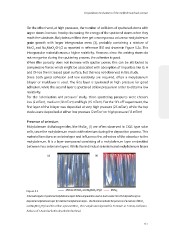
Figure 5.2
Schematic figure of sputtered molybdenum layers before degradation used as back contact for CIGS deposition (a) as
deposited molybdenum layer (b) selenised molybdenum layer - The blue lines indicate the presence of a mixture of MoO 3
and Na 2 MoO 4 •2H 2 O and the red lines represent MoSe 2 . These samples were deposited for 47 minutes at 15 mTorr, and have a
thickness of: 1.8 μm (not further described in this thesis).
133
On the other hand, at high pressures, the number of collisions of sputtered atoms with
argon atoms increase, hereby decreasing the energy of the sputtered atoms when they
reach the substrate. Molybdenum films then get a more porous columnar molybdenum
grain growth with larger intergranular areas [3], probably containing a mixture of
MoO and Na MoO •2H O as reported in reference [15] and shown in Figure 5.2a. This
2
4
3
2
intergranular material causes a higher resistivity. However, since the arriving atoms do
not reorganise during the sputtering process, the adhesion is good.
When film porosity does not increase with sputter power, this can be attributed to
compressive forces which might be associated with absorption of impurities like O, H
and OH on the increased grain surface, but this was not observed in this study.
Since both good adhesion and low resistivity are required, often a molybdenum
bilayer or multilayer is used. The first layer is sputtered at high pressure for good
adhesion, while the second layer is sputtered at low pressure in order to obtain a low
resistivity.
For the ‘selenisation and pressure’ study, three sputtering pressures were chosen:
low (2 mTorr), medium (10 mTorr) and high (15 mTorr). For the ‘lift-off’ experiment, the
first layer of the bilayer was deposited at very high pressure (25 mTorr), while the top
stacks were deposited at either low pressure (2 mTorr) or high pressure (15 mTorr)
Presence of selenium
Molybdenum dichalcogenides, like MoSe [1] are often observed in CIGS type solar
2
cells, since the molybdenum reacts with selenium during the deposition process. This
material functions as an interlayer and influences the adhesion of the absorber to the
molybdenum. It is a layer compound consisting of a molybdenum layer embedded
between two selenium layers. While the individual selenium and molybdenum layers
(a) (b)
Figure 5.2
Schematic figure of sputtered molybdenum layers before degradation used as back contact for CIGS deposition (a) as
deposited molybdenum layer (b) selenised molybdenum layer - The blue lines indicate the presence of a mixture of MoO 3
and Na 2 MoO 4 •2H 2 O and the red lines represent MoSe 2 . These samples were deposited for 47 minutes at 15 mTorr, and have a
thickness of: 1.8 μm (not further described in this thesis).
133