Page 136 - Mirjam-Theelen-Degradation-of-CIGS-solar-cells
P. 136
Chapter 5
are covalently bonded, the Se/Mo/Se triple layers are bound together by weak Van
der Waals forces.
A CIGS/Mo contact without MoSe is a Schottky-type contact, while the introduction
2
of MoSe leads to a change into a beneficial ohmic-type contact. MoSe may be
2
2
incorporated in a molybdenum matrix is through its presence in the intergrain area,
as shown in Figure 5.2b. A similar structure was reported in reference [16] for MoS .
2
Since this MoSe layer is present in CIGS solar cells, it should also be taken into
2
account for the degradation of CIGS. In the ‘selenisation and pressure’ study, half of
the samples were selenised with a recipe resembling the selenisation conditions in a
typical coevapouration process.
In the ‘lift-off’ study, a CIGS layer was first deposited on the molybdenum, creating a
SLG/Mo/MoSe /CIGS stack. After this, the CIGS layer was removed, so a SLG/Mo/MoSe
2
2
layer remained.
5.3.1 Selenisation and pressure experiment
5.3.1.1 Initial layer properties
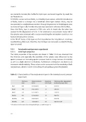
The initial properties of the samples are shown in Table 5.3 . It was observed that
the thickness and especially the resistivity of the sample were influenced by the
sputter pressure: an increasing sputter pressure leads to a large increase of resistivity
as well as a slight decrease in thickness. Furthermore, selenisation also leads to an
increase in initial resistivity. These values can be compared with the resistivity of bulk
molybdenum, which is 5.3x10⁻⁶ Ωcm (http://nl.wikipedia.org/wiki/Molybdeen)
Table 5.3 Characteristics of the molybdenum layers in the ‘selenisation and pressure’
experiment.
Thickness Sheet resistance Resistivity Thickness after degradation
(nm) (Ω/☐) (x10 Ωcm) bottom/top layer (nm)
-5
Mo2 880 0.180±0.003 1.6 850/310
Mo10 740 0.437±0.010 3.2 580/350
Mo15 770 0.737±0.021 5.7 520/530
Mo2Se 910 0.214±0.003 2.0 940/170
Mo10Se 870 0.606±0.019 5.3 830/200
Mo15Se 620 1.439±0.031 9.0 540/130+520*
* This indicates the formation of two distinguishable layers, as visible in Figure 5.6
134
are covalently bonded, the Se/Mo/Se triple layers are bound together by weak Van
der Waals forces.
A CIGS/Mo contact without MoSe is a Schottky-type contact, while the introduction
2
of MoSe leads to a change into a beneficial ohmic-type contact. MoSe may be
2
2
incorporated in a molybdenum matrix is through its presence in the intergrain area,
as shown in Figure 5.2b. A similar structure was reported in reference [16] for MoS .
2
Since this MoSe layer is present in CIGS solar cells, it should also be taken into
2
account for the degradation of CIGS. In the ‘selenisation and pressure’ study, half of
the samples were selenised with a recipe resembling the selenisation conditions in a
typical coevapouration process.
In the ‘lift-off’ study, a CIGS layer was first deposited on the molybdenum, creating a
SLG/Mo/MoSe /CIGS stack. After this, the CIGS layer was removed, so a SLG/Mo/MoSe
2
2
layer remained.
5.3.1 Selenisation and pressure experiment
5.3.1.1 Initial layer properties
The initial properties of the samples are shown in Table 5.3 . It was observed that
the thickness and especially the resistivity of the sample were influenced by the
sputter pressure: an increasing sputter pressure leads to a large increase of resistivity
as well as a slight decrease in thickness. Furthermore, selenisation also leads to an
increase in initial resistivity. These values can be compared with the resistivity of bulk
molybdenum, which is 5.3x10⁻⁶ Ωcm (http://nl.wikipedia.org/wiki/Molybdeen)
Table 5.3 Characteristics of the molybdenum layers in the ‘selenisation and pressure’
experiment.
Thickness Sheet resistance Resistivity Thickness after degradation
(nm) (Ω/☐) (x10 Ωcm) bottom/top layer (nm)
-5
Mo2 880 0.180±0.003 1.6 850/310
Mo10 740 0.437±0.010 3.2 580/350
Mo15 770 0.737±0.021 5.7 520/530
Mo2Se 910 0.214±0.003 2.0 940/170
Mo10Se 870 0.606±0.019 5.3 830/200
Mo15Se 620 1.439±0.031 9.0 540/130+520*
* This indicates the formation of two distinguishable layers, as visible in Figure 5.6
134